A) E2 + R3I3 + E3 - R2I2 = 0
B) E2 + R3I3 - E3 + R2I2 = 0
C) E2 - R3I3 - E3 - R2I2 = 0
D) E2 + R3I3 + E3 + R2I2 = 0
E) -E2 + R3I3 - E3 + R2I2 = 0
Correct Answer

verified
B
Correct Answer
verified
Multiple Choice
A small galvanometer coil of resistance R = 20 Ω and full-scale deflection at 1 mA is connected in series with a 4980 Ω resistance to build an analog voltmeter. What is the maximum voltage that this voltmeter can read?
A) 3 V
B) 1 V
C) 50 V
D) 5 V
E) 10 V
Correct Answer

verified
D
Correct Answer
verified
Multiple Choice
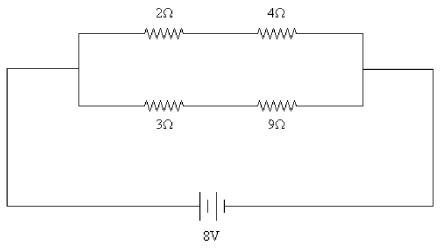
FIGURE 26-24  -Four resistors of values 2 Ω, 4 Ω, 3 Ω, and 9 Ω are connected across an 8-V DC source as shown in Fig. 26-24. What is the current through the 9-Ω resistor?
A) 1 A
B) 0.7 A
C) 0.5 A
D) 0.9 A
E) 2 A
Correct Answer

verified
Correct Answer
verified
True/False
Four equal resistors connected across a DC voltage source in either series or parallel will have equal voltage drops across each resistor.
Correct Answer

verified
Correct Answer
verified
Multiple Choice
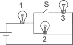
FIGURE 26-1  -Fig. 26-1 shows three identical lightbulbs connected to a battery. What happens to the brightness of lightbulb 1 when the switch S is closed?
A) The brightness will increase momentarily then return to its previous level.
B) The brightness increases.
C) The brightness will decrease momentarily then return to its previous level.
D) The brightness remains the same as before the switch is closed.
E) The brightness decreases.
Correct Answer

verified
Correct Answer
verified
Multiple Choice
A 4.0-μF capacitor is charged to 6.0-V. It is then connected in series with a 3.0-MΩ resistor and connected to a 12-V battery. How long after being connected to the battery will the voltage across the capacitor be 9.0 V?
A) 5.5 s
B) 7.2 s
C) 8.3 s
D) 12 s
E) 17 s
Correct Answer

verified
C
Correct Answer
verified
Multiple Choice
An analog ammeter able to have a 0.5 A maximum reading is to be built using a small coil of resistance R = 20 Ω, and full scale deflection at 1 mA. What resistance should be added to this coil and how should it be connected to the coil?
A) 0.08 Ω in parallel
B) 0.5 Ω in parallel
C) 0.02 Ω in series
D) 20.4 Ω in parallel
E) 0.04 Ω in parallel
Correct Answer

verified
Correct Answer
verified
Multiple Choice
You obtain a 100-W light bulb and a 50-W light bulb. Instead of connecting them in the normal way, you devise a circuit that places them in series across normal household voltage. Which statement is correct?
A) Both bulbs glow at the same reduced brightness.
B) Both bulbs glow at the same increased brightness.
C) The 100-W bulb glows more brightly than the 50-W bulb.
D) The 50-W bulb glows more brightly than the 100-W bulb.
Correct Answer

verified
Correct Answer
verified
Multiple Choice
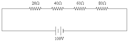
FIGURE 26-16  -A 100 V DC signal is applied to four resistors as shown in Fig. 26-16. The values of the resistors are 20 Ω, 40 Ω, 60 Ω, and 80 Ω. What is the voltage across the 40 Ω resistor?
A) 20 V
B) 40 V
C) 60 V
D) 80 V
E) 100 V
Correct Answer

verified
Correct Answer
verified
Multiple Choice
As more resistors are added in series to a constant voltage source, the power supplied by the source
A) increases.
B) decreases.
C) does not change.
D) increases for a time and then starts to decrease.
E) decreases for a time and then starts to increase.
Correct Answer

verified
Correct Answer
verified
Multiple Choice
Kirchhoff's junction rule is a statement of
A) the law of conservation of momentum.
B) the law of conservation of charge.
C) the law of conservation of energy.
D) the law of conservation of angular momentum.
E) Newton's second law.
Correct Answer

verified
Correct Answer
verified
Multiple Choice
An ideal voltmeter is one that does not change the behavior of a circuit when it is properly used to measure potential difference. The internal resistance of such a meter is
A) dependent on the circuit.
B) infinite.
C) the same resistance as the circuit.
D) 0 Ω.
E) cannot be determined
Correct Answer

verified
Correct Answer
verified
True/False
An RC circuit is connected across a DC voltage source through an open switch. As soon as the switch is closed, the capacitor charges linearly as a function of time.
Correct Answer

verified
Correct Answer
verified
Multiple Choice
In order to construct a voltmeter from a galvanometer, one normally would
A) use a very small shunt resistor.
B) use a very large shunt resistor.
C) use a very small series resistor.
D) use a very large series resistor.
Correct Answer

verified
Correct Answer
verified
True/False
The electromotive force of a battery is the maximum potential difference between the terminals of the battery.
Correct Answer

verified
Correct Answer
verified
Multiple Choice
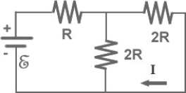
FIGURE 26-29  -In Fig. 26-29, I = 0.5 A and R = 12 Ω. What is the value of the emf E?
A) 18 V
B) 24 V
C) 6 V
D) 12 V
E) 48 V
Correct Answer

verified
Correct Answer
verified
Multiple Choice
Four unequal resistors are connected in a series circuit. Which one of the following statements is correct about this circuit?
A) The total resistance is equal to any one of the resistors.
B) The total resistance is equal to average of the four resistors.
C) The total resistance is less than the smallest resistor.
D) The total resistance is less than the largest resistor.
E) The total resistance is more than the largest resistor.
Correct Answer

verified
Correct Answer
verified
Multiple Choice
A 6-Ω resistor, an 8-Ω resistor, and a 24-Ω resistor are connected together. What is the minimum resistance that can be produced using all three resistors?
A) 4 Ω
B) (1/24) Ω
C) 3 Ω
D) (1/6) Ω
E) 7 Ω
Correct Answer

verified
Correct Answer
verified
Multiple Choice
A 2.0-μF capacitor is charged to 12 V and then discharged through a 4.0 × 10⁶ Ω resistor. How long will it take for the voltage across the capacitor to drop to 3.0 V?
A) 4.5 s
B) 8.0 s
C) 11 s
D) 22 s
E) 24 s
Correct Answer

verified
Correct Answer
verified
Multiple Choice
The potential difference between the terminals of a battery, when current flows to an external circuit, is referred to as the
A) emf.
B) terminal voltage.
Correct Answer

verified
Correct Answer
verified
Showing 1 - 20 of 110
Related Exams